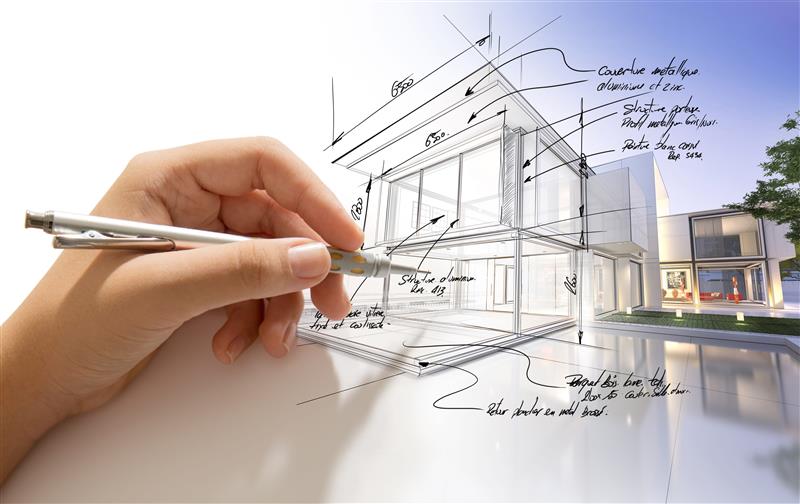
Assembly drawings function as primary communication tools connecting design teams and fabrication teams. Clear documentation ensures that intent, geometry, and build logic transfer accurately into physical production.
Errors within these drawings commonly trigger fabrication delays, increased labor costs, wasted materials, and failed inspections that require rework.
Even minor drafting inaccuracies often result in change orders, material waste, and disrupted schedules.
Adoption of BIM workflows, strict CAD standards, and structured quality control processes significantly reduces error frequency and downstream consequences.
Inaccurate Dimensions and Scale
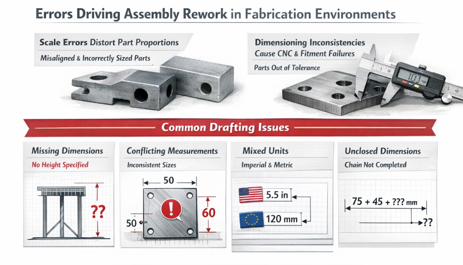
Incorrect scale usage and incomplete dimensioning consistently rank among primary drivers of assembly rework across fabrication environments.
Scale errors distort part proportions, resulting in components that fail to align during assembly or require material replacement. Improper scaling also leads to inaccurate material takeoffs, increasing waste and procurement costs.
Dimensioning inconsistencies frequently translate into CNC programming failures, hardware misalignment, and parts manufactured outside acceptable size ranges.
Several recurring drafting conditions directly contribute to these failures, including:
- Dimensions omitted in elevation or section views, while present in plans
- Conflicting measurements between related views
- Mixed imperial and metric units within a single drawing set
- Unclosed dimension chains that prevent verification and validation
Automated dimension verification tools available within BIM and CAD platforms detect conflicts early in drafting workflows, reducing downstream corrections.
Consistent unit systems maintained across entire drawing packages eliminate conversion errors during fabrication.
Field verification performed before final documentation confirms alignment with site conditions and installed constraints.
Explicit tolerance documentation for components such as drawer fronts or countertop joints ensures fabrication outcomes match design intent without forced adjustments.
Incomplete or Ambiguous Component Details
Missing component-level information introduces uncertainty during fabrication and assembly processes.
Fabricators, especially those working in high-reliability sectors such as automotive PCB, rely on drawings not only for geometry but also for build logic and sequencing.
Omitted joinery definitions, edge treatments, fastener types, and intersection geometry force assumptions that compromise finish quality and structural reliability. Lack of assembly steps or spatial references further increases interpretation risk.
Costly production delays often occur when component intent remains unclear. Addition of 3D section cuts, multi-view details, and explicit assembly guidance reduces fabrication errors significantly.
Effective drawings provide detailed component views, numbered assembly sequences, fastener callouts, and standardized symbols across all sheets to support consistent interpretation.
Poor Coordination Between Drawing Disciplines
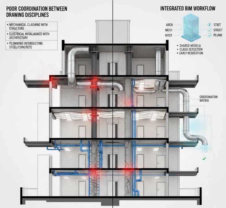
Assembly drawings typically require input across architectural, mechanical, structural.
Coordination breakdowns occur when discipline-specific drawings evolve independently, leading to physical conflicts during construction.
Ductwork intersecting beams, lighting layouts clashing with ceiling designs, and plumbing routes interfering with structural members frequently surface only after fabrication has begun.
Typical coordination failures manifest as
- Mechanical systems clashing with structural framing
- Electrical fixtures misaligned with architectural layouts
- Plumbing routes intersecting steel or concrete elements
Integrated BIM environments enable concurrent coordination across disciplines within shared models.
Clash detection tools identify conflicts during early design phases, preventing costly on-site corrections.
Regular coordination reviews maintain alignment between teams as designs evolve. Structured coordination matrices assist teams in mapping conflicts to targeted solutions such as 3D validation or real-time model adjustments.
Over-Complicated or Cluttered Drawings
Excessive detail density and poor organization reduce drawing readability.
Common issues include excessive line weights, redundant annotations, inconsistent symbols, and the placement of all objects on a single layer. Confusing drawings slow review processes and increase CNC translation errors.
Layered CAD structures with logical groupings for annotations, structure, and dimensions improve clarity. Standardized line weights and text sizes support consistent interpretation.
Use of grids and OSNAP improves accuracy during placement. Standard blocks and templates streamline repeated elements and maintain visual consistency across drawing sets.
The Bottom Line

Assembly drawing errors remain a primary contributor to fabrication rework and project inefficiency. Preventable root causes include inconsistent standards, improper CAD usage, poor coordination, and missing fabrication data.
Structured workflows, disciplined documentation practices, and multi-stage quality checks detect issues before drawings reach production floors.
Revision control protocols further protect accuracy and accountability across project lifecycles.